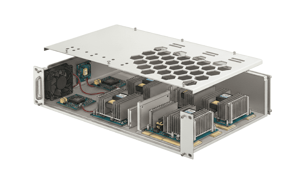
Telecommunications networks and data centers rely on far more than servers, switches, and rackmounted infrastructure. Behind the scenes, a wide range of monitoring systems, communications interfaces, power management devices, environmental sensors, and control electronics support the operation of these environments and require compact, reliable protection. That’s where PCB enclosure design comes into consideration.
Many of these products are built around compact PCB assemblies, which means enclosure selection becomes an important part of the overall design process. Board dimensions, connector placement, mounting requirements, serviceability, and deployment constraints all influence how an enclosure ultimately supports the electronics it houses.
For engineers developing these systems, the challenge is often finding an enclosure platform that provides flexibility without requiring unnecessary mechanical redesign. Lansing Instrument’s MicroPak family of aluminum PCB enclosureswas developed specifically for compact electronic instruments and PCB-based systems. Understanding how these enclosures meet the needs of these systems and the differences between the C-, D-, and E-style configurations helps engineers, OEMs, and product designers select the most effective enclosure solution for telecommunications and data center applications.
PCB Aluminum Enclosure Considerations for Telecommunications and Data Center Electronics
While telecom and data center infrastructure is often associated with large rackmounted equipment, many supporting devices occupy a much smaller footprint.
Applications such as:
- Network monitoring and diagnostics modules
- Communications interface devices
- Environmental monitoring systems
- Power distribution monitoring electronics
- Instrumentation and control modules
- Edge and remote-site electronics
all require packaging solutions that support reliable operation while fitting within existing infrastructure.
In these applications, enclosure selection is rarely driven by board dimensions alone. Engineers must also consider connector access, mounting requirements, future serviceability, installation constraints, and integration with other equipment. As a result, the enclosure becomes an important part of the overall system architecture rather than simply a protective housing.
PCB Layout and Internal Enclosure Requirements
PCB layout is one of the first considerations in enclosure design. Board dimensions, connector placement, cable routing, and internal component density all influence enclosure selection.
In telecommunications and data center applications, compact devices often combine communications modules, indicators, sensors, and power components within a limited footprint. When an enclosure cannot accommodate these requirements, engineers may find themselves redesigning boards, relocating interfaces, or compromising on usability.
MicroPak enclosures are available in multiple widths, heights, and configurable lengths, allowing enclosure dimensions to be selected around the electronics rather than forcing electronics into a predetermined package. This flexibility helps reduce design iterations while maintaining a consistent enclosure platform for monitoring, communications, and control systems.
End Panel and Interface Accessibility
In telecommunications and data center environments, front- and rear-panel access frequently determines how equipment is installed, maintained, and serviced.
Depending on the application, engineers may need to accommodate:
- Ethernet ports
- Fiber interfaces
- Power connections
- Status indicators
- Configuration ports
- Monitoring interfaces
These interface requirements often drive enclosure selection as much as the PCB itself.
MicroPak offers multiple end-panel configurations that support a variety of interface layouts, allowing engineers to align enclosure design with the specific needs of the electronics. Whether the application requires simple connector access or more complex panel arrangements, enclosure configuration can support usability without compromising integration.
Considering EMI and RFI Requirements
For some telecommunications and data center applications, electromagnetic interference (EMI) and radio frequency interference (RFI) shielding considerations can influence enclosure selection alongside mechanical requirements.
Communications interfaces, monitoring equipment, and densely populated PCB assemblies may require enclosure configurations that support broader electromagnetic compatibility (EMC) objectives.
Because MicroPak enclosures are manufactured from aluminum, they provide inherent shielding characteristics that can help reduce the transmission of electromagnetic interference compared to non-metallic enclosure alternatives. For applications with more demanding EMC requirements, additional shielding options can also be incorporated into the enclosure design.
By considering shielding requirements early in the design process, engineers can address both electrical and mechanical requirements while maintaining flexibility in mounting, panel layout, and overall enclosure configuration.
Precision Machining Supports Application-Specific Requirements
Front and rear panels are often where enclosure requirements become application-specific.
Connector cutouts, display windows, mounting features, labeling, ventilation requirements, and branding elements can vary significantly from one product to the next.
Lansing supports custom machining and panel modifications that allow standard enclosure designs to be adapted to specific product requirements. This approach combines the efficiency of a standard enclosure platform with the flexibility needed for specialized electronics used in telecommunications and infrastructure environments.
Rack-Based Integration and Deployment Flexibility
Many compact electronic systems need to be integrated into rack-based equipment.
Rather than developing a dedicated rack enclosure, engineers often prefer solutions that allow modules or subassemblies to be integrated into existing or standard rackmount panels.
MicroPak enclosures support this requirement through 23 standard rackmount panel configurations, referenced by enclosure width (N, Q, E, T, or W). These configurations allow compact PCB-based electronics to be integrated into standard 19-inch rack environments.
This range of mounting options provides flexibility for deploying applications such as network monitoring equipment, communications interfaces, and control electronics within rack environments without creating an entirely new enclosure architecture.
Comparing the MicroPak Family: C-Style vs. D-Style vs. E-Style
While all MicroPak enclosures are designed to support compact, precision electronics, each style addresses different integration priorities through its enclosure construction, panel configurations, mounting capabilities, and available accessories.
C-Style MicroPak Enclosures
The C-Style MicroPak enclosure is the original and most economical design in the MicroPak family, built with a rugged aluminum body, extruded base, and formed slide-on cover. Available in 7 standard sizes with multiple height and width combinations and standard lengths that can be extended through custom ordering, it is designed for broad PCB integration and electronic control applications, including Eurocard (E-width) compatibility.
Its strength lies in configuration flexibility, offering multiple end options such as end panel/bezel combinations, molded polycarbonate end caps, or an integrated 9-volt battery compartment. Internal mounting options, non-skid feet, and a recessed labeling area further support adaptable system integration across a wide range of applications.
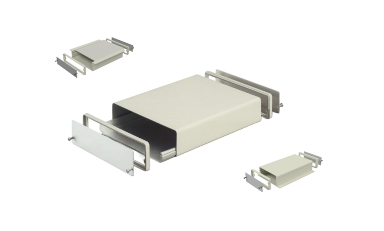
D-Style MicroPak Enclosures
The D-Style MicroPak enclosure features a simplified one-piece seamless extruded aluminum tube design, making it the most streamlined option in the family. It is well suited for modular and rack-mounted systems, especially when used with a MicroPak rackmount panel for isolated or independently serviced units.
Available in 6 standard sizes with configurable lengths, the D-Style is designed for embedded and instrumentation systems requiring efficient PCB integration via internal slide-in mounting slots. Configuration options include end panel/bezel combinations, molded polycarbonate end caps, or extended metal end panels, along with an optional 9-volt battery compartment.
Additional features such as non-skid feet and multiple finish options enhance versatility while maintaining a clean, minimal enclosure structure.
E-Style MicroPak Enclosures
The E-Style MicroPak enclosure is designed for highly compact electronic systems where a streamlined enclosure and efficient use of space are primary considerations. It features a rugged aluminum construction with an extruded base and a flat, slide-in top panel that maximizes usable surface area for interface design and labeling.
Available in 6 standard sizes with multiple height and width combinations, and standard front-to-back lengths within each size (with custom lengths available upon request), the E-Style supports a range of compact instrumentation and embedded applications.
Each enclosure can be configured with multiple end options, including end panel/bezel combinations (the most versatile option available across all sizes), solid molded polycarbonate end caps, or an integrated 9-volt battery compartment with sliding access cover. Top panels are offered in two thickness options with a variety of finishes to support both functional and aesthetic requirements, while additional features such as non-skid feet and optional rack-mount panel compatibility enhance installation flexibility.
Feature Comparison
| Feature | C-Style | D-Style | E-Style |
| Size Range (L) × (W) × (H) | (6” to 9”) x (2.75” to 7.29”) x (1.12” to 2.52”) | (3” to 7”) x (2.75” to 5.53”) x (0.75” to 1.52”) | (5” to 7”) x (2.75” to 5.53”) x (0.75” to 1.52”) |
| Material | Base: Extruded Aluminum | Base: Extruded Aluminum | Base: Extruded Aluminum |
| Cover: Finished Aluminum, Vinyl-Clad Steel | Cover: Extruded Aluminum | Cover: Finished Aluminum, Vinyl-Clad Aluminum | |
| Panels: Aluminum, Vinyl-Clad Aluminum or Polycarbonate | Panels: Aluminum, Vinyl-Clad Aluminum or Polycarbonate | Panels: Aluminum, Vinyl-Clad Aluminum or Polycarbonate | |
| Standard Colors | Pearl White, Platinum, Medium Gray, Black | ||
| Finish | Textured | Textured | Textured or Smooth |
| Mounting Options | PCB mounts or panel mounts | Internal PCB guides, optional flanged extrusion | Optional flanges |
| Accessories | Gaskets, screws, optional transparent lids | PCB rails, internal mounting bosses | Captive covers, internal fasteners |
Selecting the Right MicroPak Enclosure Platform for Telecommunications and Data Center Applications
Telecommunications and data center electronics often require enclosure solutions that balance PCB integration, interface access, shielding considerations, mounting flexibility, and long-term serviceability.
With configurable dimensions, precision machining capabilities, rack integration options, and multiple enclosure styles, Lansing’s MicroPak family provides a flexible platform for monitoring, communications, instrumentation, and control electronics. Because MicroPak uses a modular enclosure architecture, engineers can adapt dimensions, panel configurations, and mounting options as product requirements evolve.
Explore Lansing’s MicroPak enclosure options to compare available sizes, mounting configurations, end panel options, and customization capabilities for your next telecommunications or data center application.